Software
The OBDH board has a MSP430 microcontroller that manages the others sub-modules in the board. This section describes the developed software to this device.
System Overview
The programming language used is C. All software was developed in the Code Composer Studio IDE (v6.1.3.00034), a.k.a. CCS.
The OBDH module has to do many tasks, such interfacing peripherals and another MCUs, over distinct protocols and time requirements. Because of that, it needs a Real Time Operating System to assure that it will deal with its deadlines, even under a fault in some task routine. The RTOS chosen is FreeRTOS (v9.0.0), since it is designed for embedded systems and it was already validated in space applications.
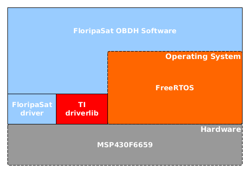
The software was made to have some abstraction layers. This is reached using drivers to manage internal peripherals, such as GPIO, watchdog timers, timers, clocks, USCIs and ADCs. For this purpose it was used the "MSP Driver Library" library, provided by TI, also know as "DriverLib". Aiming to full cover the software needs, some peripheral drivers was developed too. The figure below illustrates the overall software topology.
Software flow
- Watchdog configuration
- Setup Hardware
- Create tasks
3.1. Antenna deployment interface
3.2. EPS interface
3.3. Ground Communications
3.4. IMU interface
3.5. Read internal sensors
3.6. Store data
3.7. Solar panels interface
3.8. Reset Watchdog timers - Start scheduler
After the step 4, the system will schedule the tasks to execute, according some OS definitions like scheduling type and each task priority. So, there isn't just one execution flow.
Operating System
FreeRTOS's task scheduler can be set up to work in preemptive or cooperative mode. For OBDH, the preemptive mode was chosen. In preemptive mode a task can be interrupted in the middle of it execution, because a OS event, for instance. In cooperative mode a task just leave the processor when it finishes it execution. Other way is if a task request to leave the processor. "Leave the processor" means stop to use it, which let it free to another tasks. When the processor is free, the next task to use it is the next in a queue, ordered by its priorities. So, the most important tasks may be at the beginning of the queue. This allows us to overweight the mandatory jobs, to assure that a fault in a less relevant task do not compromise the mission. When a task be ready again to executes, it is putted in the queue, according its priority.
Tasks description:
This subsection will describes the functionality and behavior of each OBDH's task.
Antenna deployment interface
Communicates with the Antenna module and do it deployment. The communication interface with antenna is I2C.
EPS interface
This task is responsible to trade messages with the EPS module. This communication is done over SPI protocol. The purpose of this message could be: sensors data trading, notify to each other about its current status, do handshaking about some necessary shutdown, among others integration commands.
Ground Communications
Handle the ground-space communications. To transmit, assemble the data (sensors data, current time, reset events, received messages, peripheral status, among others) and send, over SPI protocol, to the radio transceiver. In a reception, decodes the payload of the packet, verify its authenticity and operates according the received command.
IMU interface
Read the 2 on-board IMUs. Each IMU has a 3-axis Accelerometer, 3-axis Gyroscope and 1 temperature sensor. This data is necessary to allow the Attitude Control in ADCS module. The both IMU are in a I2C bus.
Read internal sensors
Read the MSP's internal sensors. The internal temperature sensor, the supply voltage and the current consumption is readed over the internal ADC.
Store data
To avoid that a reset causes lost of data, the data persistence is made on a non-volatile memory. Some events, like a unexpected resets or received messages, are written in a log event. Then (in Ground Communications task) this data could be sent over downlink. The connection with the non-volatile memory is over a SPI interface.
Solar panels interface
Read the solar panels sensors over a SPI interface. There are different types of solar panels, some have extra sensors like 1-axis gyroscope and 1-axis accelerometer, while anothers have a sun sensor and a temperature sensor.
Reset Watchdog timers
A strategy to avoid a deadlock (software lock in some code stretch) 2 watchdog is used: 1 internal and 1 external. This task will run periodically and reset the watchdog timers, so, if a lock occurs, the reset will not happen and the watchdog will reset the MCU. There are 2 watchdog to bring redundancy for the system.
Universal Serial Communication Interfaces (USCIs) Configuration
The OBDH main characteristic is concentrate and manage the data flow. Because of that, the definition of the communication interfaces are a important stage of the cubesat. The table below presents the 6 MSP USCIs modules, which its definitions and connected components.
| MSP INTERFACE | MODE | CONNECTED COMPONENTS |
|---|---|---|
| USCI_A0 | SPI | Radio Transceiver |
| USCI_A1 | SPI | SPI MAIN BUS (Non-volatile memory, Solar Panels) |
| USCI_A2 | UART | DEBUG |
| USCI_B0 | I2C | MAIN I2C BUS(OBDH, EPS, Payloads) |
| USCI_B1 | I2C | IMU's I2C BUS (IMU1, IMU2) |
| USCI_B2 | I2C | Antenna Deployment |
Debug mode
A UART interface is provided to print log messages for debugging purpose. A UART-USB converter (FTDI chip for example) can be used with the follow configuration:
- Baud rate = 9600 bps
- Data bits = 8
- Parity bit = None
- Stop bits = 1