Subsystem Tests
MSP430F249 internal ADC
This test's aim is to validate the msp430f249 internal ADC, which is used to measure the voltages and currents on the solar panels.
Test procedure:
- connect 6.0V source to Vbus and connect source GND to GND pin on the EPS board
- connect source to be measured to the desired channel of the ADC (Panel -Y for channel 0, Panel -X for channel 2, Panel -Z for channel 4 and either -L8,-L9 or -L10 for channel 6). Voltage drops on diodes and voltage dividers must be taken into account. For channel 1, 3 and 5 currents are measured through the current sensors. To make these measurements, connect a resistor as load on +L8 to GND for channel 1, +L9 to GND for channel 3 and +L10 to GND for channel 5. The source in this measurements must set current and not voltage. For this test two resistors of 47Ω and power rating 5W are connected in series.
- connect msp430fet from CCS to board
- program the msp430f249 with code eps_ADC_test.c
- run the code and verify if values are correct on the ADC12MEMx registers in CCS
Test results: The results show 5 measurements taken for each channel
| Channel | Input | Output |
|---|---|---|
| 0 | 1.5V | 1.467V; 1.462V; 1.464V; 1.467V; 1.469V |
| 1 | 0.050A | 0.0506A; 0.0506A; 0.0512A; 0.0506A; 0.0512A |
| 2 | 1.5V | 1.452V; 1.455; 1.452; 1.455; 1.452 |
| 3 | 0.050A | 0.0509A; 0.0490A; 0.0514A; 0.0509A; 0.0506A |
| 4 | 1.5V | 1.464V; 1.462; 1.464; 1.464; 1.462 |
| 5 | 0.050A | 0.0504A; 0.0495A; 0.0509A; 0.0499A; 0.0499A |
| 6 | 1.5V | 1.469V; 1.469V; 1.467V; 1.469V; 1.467V |
Better results can be achieved by taking the mean of the measurements over a time.
Battery Heater P controller
This test aims to validate an initial controller for the battery heater, with only a proportional term. The expected result is a steady state error with a constant duty cycle.
Test procedure:
1. Connect source 3.3V to 3V3_BEACON_EPS pin on EPS board.
2. Connect source 8V to VBUS pin on EPS board.
3. Connect source GND to GND pins on EPS board.
4. Compile and download bat_heater project to EPS board with P factor configured to 250, I factor configured to 0 and D factor configured to 0 and setpoint configured to the desired value.
5. Run code and acquire the results via UART.
The results are in the following graph:
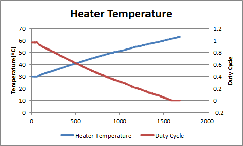
As expected the temperature increases with time and the duty cycle decreases. In this test the setpoint was 45ºC, as we can see from the graph there is a big steady state error.
Battery Heater PI controller
This test aims to validate a controller for the battery heater with a proportional term and an integral term. The expected result is no steady state error with overshoot.
Test procedure:
1. Connect source 3.3V to 3V3_BEACON_EPS pin on EPS board.
2. Connect source 8V to VBUS pin on EPS board.
3. Connect source GND to GND pins on EPS board.
4. Compile and download bat_heater project to EPS board with P factor configured to 250, I factor configured to 20 and D factor configured to 0 and setpoint configured to the desired value. Also make sure that the max sum error is compatible with max I term and max PID.
5. Run code and acquire the results via UART.
The results are in the following graph:
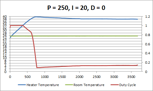
As expected there is a 2ºC overshoot and no steady state error.
PA Regulators
This test's goal is to verify the PA regulators under a pulsed load condition.
Test Procedeure:
 1. Connect source 8V to Vbus pin on EPS board.
 2. Connect source GND to GND pins on EPS board.
 3. Connect electronic load to 3V3_PA_TT&C or 3V3_PA_Beacon depending on the regulator in test.
 4. Configure electronic load to ARB mode with pulses of 1s and 3A amplitude.
The test results are in the following graph:
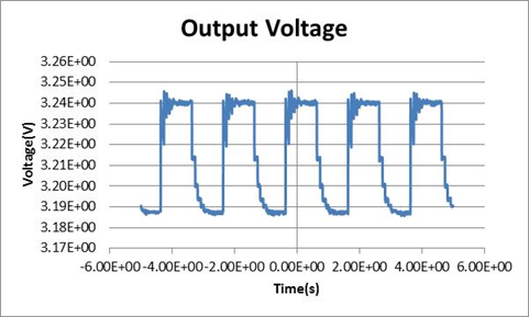 As expected the voltage is near 3.3V when there is no load and drops to about 3.19V when there is a 3A load.
Other tests with different load amplitudes/durations show similar results.
As expected the voltage is near 3.3V when there is no load and drops to about 3.19V when there is a 3A load.
Other tests with different load amplitudes/durations show similar results.
Payload Regulators
This test's goal is to verify the payload regulators under a pulsed load condition.
 Test Procedeure:
 1. Connect source 8V to Vbus pin on EPS board.
 2. Connect source GND to GND pins on EPS board.
 3. Connect electronic load to 5V_P1 or 5V_P2 depending on the regulator in test.
 4. Configure electronic load to ARB mode with pulses of 1s and 3A amplitude.
The test results are in the following graph:
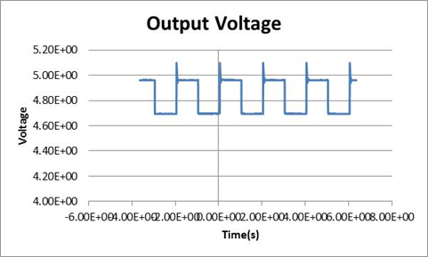 The voltage is around 5V when the load is 0 and around 4.7V when the load is 3A. There is also a ~0.1V overshoot when the load switches.
Other test with different load amplitudes/durations show similar results.
The voltage is around 5V when the load is 0 and around 4.7V when the load is 3A. There is also a ~0.1V overshoot when the load switches.
Other test with different load amplitudes/durations show similar results.